An ancient technology, a modern frontier
Biomass gasification is not a technology of the future: its roots go back to the 19th century, when "town gas" obtained from coal carbonisation lit streets and homes throughout Europe. During the Second World War, more than a million European vehicles ran on wood gasifiers mounted on the bonnet, a pragmatic response to the scarcity of fossil fuels.
What has changed radically is our ability to control the process, measure its parameters in real time and integrate it into high-efficiency micro-cogeneration systems. The gasifier of the BioGS-1.0 is the direct heir to that technology, re-engineered with digital tools and modern materials to achieve reliability and performance unimaginable for the 1940s versions.
The thermochemical process: four zones, one transformation
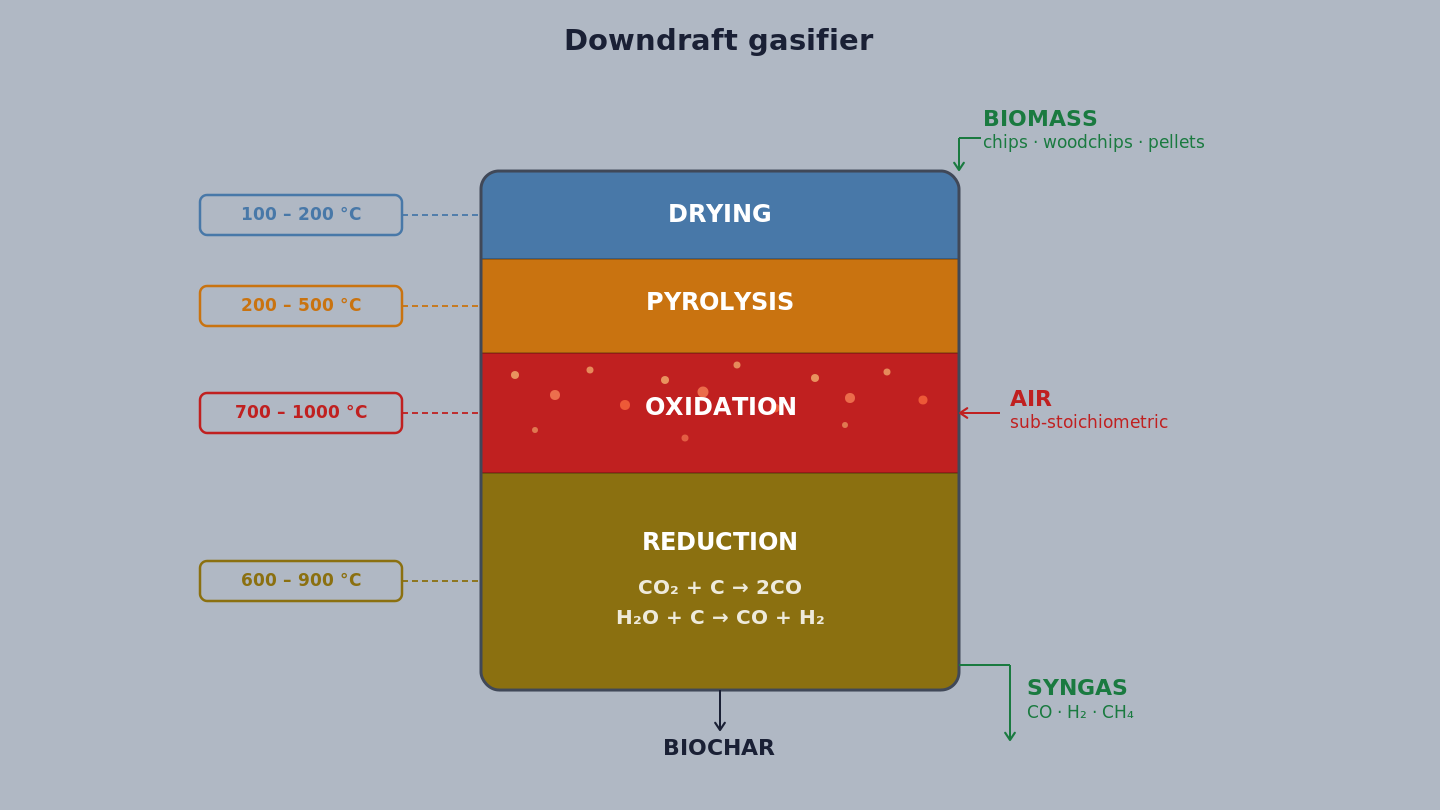
Inside the gasification reactor, four distinct thermochemical processes take place in sequence, each in a separate zone:
- Drying zone (100–200 °C): incoming biomass loses residual moisture through evaporation. The BioGS-1.0 accepts biomass up to 10% moisture without mandatory pre-drying.
- Pyrolysis zone (200–500 °C): dry biomass decomposes thermally, producing char, condensable vapours (tar) and non-condensable gases (CO, CO₂, CH₄, H₂).
- Oxidation zone (700–1,000 °C): process air is introduced in controlled quantities. Partial combustion of char and gases brings temperatures to the process peak, essential for thermal tar cracking.
- Reduction zone (600–900 °C): high-temperature gases react with residual char in endothermic reactions: CO₂ + C → 2CO (Boudouard reaction) and H₂O + C → CO + H₂ (water-gas shift reaction). This is where high-quality syngas is formed.
The final product is a syngas with a typical composition: CO 15–20%, H₂ 10–15%, CH₄ 3–5%, CO₂ 10–15%, N₂ (balance), with a lower heating value of 4.5–5.5 MJ/Nm³.
Reactor geometry: updraft, downdraft, crossdraft
The geometric configuration of the reactor fundamentally determines the quality of the syngas produced, in particular the tar content, the primary cause of operational problems in small-scale gasification systems.
- Updraft (counter-current): biomass descends from above while air rises from below. Syngas exits at the top, at low temperature, carrying large quantities of condensable tar (50–150 g/Nm³). High thermal efficiency but "dirty" syngas.
- Crossdraft: air enters laterally and syngas exits from the opposite side. Very short reaction times, suitable for dry, uniform biomasses (charcoal). Low tolerance to fuel variation.
- Downdraft (co-current): biomass descends and air enters the oxidation zone; syngas passes through the reduction zone and high temperatures before exiting at the bottom. Tar is thermally cracked in the hot zone, exiting at typical concentrations of 0.5–5 g/Nm³, significantly lower than updraft. This is the configuration chosen for the BioGS-1.0 system.
Open core gridless: KiRa's qualitative leap
The conventional downdraft gasifier has a weak point: the metal grate at the bottom of the reactor, which supports the fuel bed and distributes reduction air. Grates become clogged, deform through thermal fatigue, require frequent maintenance and limit the acceptable biomass type, they cannot handle biomasses with a high fusible ash content or fine particles.
The BioGS-1.0 adopts an open core gridless geometry: the reactor has no grate. Biomass and char pass through the oxidation zone unobstructed. The reduced char is extracted from the bottom of the reactor via an automatic discharge system.
The operational advantages are significant:
- tolerance to heterogeneous biomasses;
- elimination of the primary cause of unscheduled downtime (grate clogging);
- reduction of maintenance interventions;
- better distribution of biomass flow in the reduction zone.