

An ancient technology, a modern frontier
Biomass gasification is not a technology of the future: its roots go back to the 19th century, when "town gas" obtained from coal carbonisation lit streets and homes throughout Europe. During the Second World War, more than a million European vehicles ran on wood gasifiers mounted on the bonnet, a pragmatic response to the scarcity of fossil fuels.
What has changed radically is our ability to control the process, measure its parameters in real time and integrate it into high-efficiency micro-cogeneration systems. The gasifier of the BioGS-1.0 is the direct heir to that technology, re-engineered with digital tools and modern materials to achieve reliability and performance unimaginable for the 1940s versions.
Why gasify
Converting biomass into a combustible gas, syngas, offers both energy and environmental advantages.
- More efficient and cleaner combustion: burning a gas allows better control of the air mixture and higher temperatures, which raise the efficiency of the Stirling thermodynamic cycle and reduce emissions compared with direct combustion of solid biomass.
- Biochar: what remains of the biomass after syngas production is a stable char, which locks away part of the carbon and can return to the soil as a soil amendment. It makes the process carbon negative and generates an additional useful product (in-depth article on biochar and FAQ).
The thermochemical process: four zones, one transformation
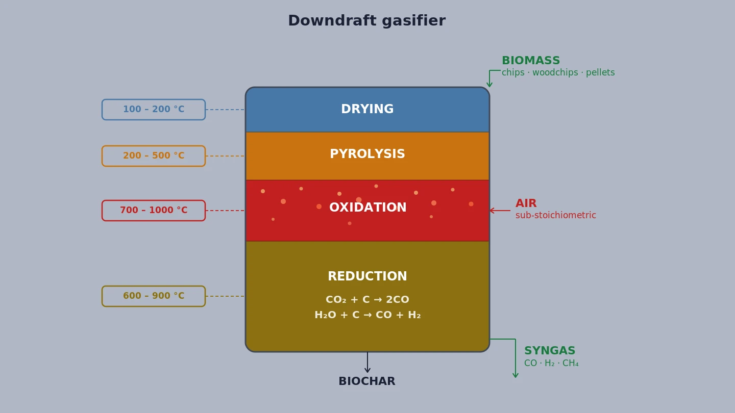
Inside the gasification reactor, four distinct thermochemical processes take place in sequence, each in a separate zone:
- Drying zone (100–200 °C): incoming biomass loses residual moisture through evaporation. The BioGS-1.0 accepts biomass up to 10% moisture without mandatory pre-drying.
- Pyrolysis zone (200–500 °C): dry biomass decomposes thermally, producing char, condensable vapours (tar) and non-condensable gases (CO, CO₂, CH₄, H₂).
- Oxidation zone (700–1,000 °C): process air is introduced in controlled quantities. Partial combustion of char and gases brings temperatures to the process peak, essential for thermal tar cracking.
- Reduction zone (600–900 °C): high-temperature gases react with residual char in endothermic reactions: CO₂ + C → 2CO (Boudouard reaction) and H₂O + C → CO + H₂ (water-gas shift reaction). This is where high-quality syngas is formed.
The final product is a syngas with a typical composition: CO 15–20%, H₂ 10–15%, CH₄ 3–5%, CO₂ 10–15%, N₂ (balance), with a lower heating value of 4.5–5.5 MJ/Nm³.
Reactor geometry: updraft, downdraft, crossdraft
The geometric configuration of the reactor fundamentally determines the quality of the syngas produced, in particular the tar content, the primary cause of operational problems in small-scale gasification systems.
- Updraft (counter-current): biomass descends from above while air rises from below. Syngas exits at the top, at low temperature, carrying large quantities of condensable tar (50–150 g/Nm³). High thermal efficiency but "dirty" syngas.
- Crossdraft: air enters laterally and syngas exits from the opposite side. Very short reaction times, suitable for dry, uniform biomasses (charcoal). Low tolerance to fuel variation.
- Downdraft (co-current): biomass descends and air enters the oxidation zone; syngas passes through the reduction zone and high temperatures before exiting at the bottom. Tar is thermally cracked in the hot zone, exiting at typical concentrations of 0.5–5 g/Nm³, significantly lower than updraft. This is the configuration chosen for the BioGS-1.0 system.
Open core gridless: KiRa's qualitative leap
The conventional downdraft gasifier has a weak point: the metal grate at the bottom of the reactor, which supports the fuel bed and distributes reduction air. Grates become clogged, deform through thermal fatigue, require frequent maintenance and limit the acceptable biomass type, they cannot handle biomasses with a high fusible ash content or fine particles.
The BioGS-1.0 adopts an open core gridless geometry: the reactor has no grate. Biomass and char pass through the oxidation zone unobstructed. The reduced char is extracted from the bottom of the reactor via an automatic discharge system.
The operational advantages are significant:
- tolerance to heterogeneous biomasses;
- elimination of the primary cause of unscheduled downtime (grate clogging);
- reduction of maintenance interventions;
- better distribution of biomass flow in the reduction zone.
Silica and ash: the limit of herbaceous biomass
When choosing a biomass, besides moisture, calorific value and particle size, the composition of the ash also matters, in particular its content of silica (SiO₂), potassium (K₂O) and sodium (Na₂O).
Wood generally produces little ash (about 0.3% of dry matter, up to 4-5% for bark) rich in calcium, an element that helps keep the melting temperature high. Herbaceous biomass, such as straw and miscanthus, produces larger amounts of ash (typically 4-7%), with higher concentrations of silica and alkalis. Silicon accounts for 4-11% of the ash of spruce chips and 16-30% of that of wheat or rye straw; in rice husk, silica can exceed 90% of the ash.
An ash rich in silica and alkalis can cause two distinct problems:
- Clinker in the reactor: silica, potassium and sodium can form silicates and low-melting eutectic mixtures. Some phases begin to melt as early as 600 to 700 °C, producing glassy agglomerates that obstruct the passage of gases. Since the BioGS-1.0 operates between 700 and 1,000 °C, these phenomena can occur within the operating range.
- Glassy deposits on surfaces in contact with the gases: in gasification most of the mineral fraction remains in the biochar and in the residual ash, but the syngas can carry fine particulate and volatile species. Potassium can evaporate at high temperature and condense on colder surfaces. In the presence of water vapour, moreover, a fraction of the silicon can be transported as orthosilicic acid, according to the reaction SiO₂(s) + 2 H₂O(g) ⇌ Si(OH)₄(g); when the gases cool in contact with lower-temperature surfaces, the reverse reaction favours the redeposition of silica. Together with alkali aerosols and fine particulate, hard, adherent layers form, made up of potassium silicates and amorphous glassy phases, which reduce heat exchange, narrow the gas passages and increase maintenance. KiRa's experience has shown that, in the most severe cases, these deposits can obstruct the gas flow to the point of compromising the restart of the plant after cooling.
In practice:
- Rice husk, cereal straw, miscanthus and energy grasses: ash very rich in silica and alkalis, with a high tendency to clinker and glassy deposits; not suitable for continuous use in the BioGS-1.0.
- Grape pomace and vine prunings: high potassium content; to be assessed case by case with an ash analysis.
- Shells and stones: variable ash composition; generally usable in a blend, checking the percentage relative to the wood pellet.
- Wood, pruning residues and lignocellulosic residues: ash low in silica and with a generally higher melting temperature; these are the preferred biomass for the BioGS-1.0.
As a practical reference, ENplus certification sets the following limits for wood pellet:
- Class A1: ash ≤ 0.7%, ash deformation temperature ≥ 1,200 °C;
- Class A2: ash ≤ 1.2%, deformation temperature ≥ 1,100 °C;
- Class B: ash ≤ 2.0%, deformation temperature ≥ 1,100 °C.
A higher ash content does not in itself make a biomass unsuitable, but it increases the importance of the chemical composition of the ash and its melting temperature: with herbaceous biomass the risk often depends more on silica and alkalis than on the amount of ash alone.
The BioGS-1.0 does not necessarily require ENplus-certified pellet. For pellet made from farm biomass other than wood, or for blends with herbaceous biomass, however, a preliminary ash analysis before continuous use is strongly recommended, paying particular attention to:
- SiO₂ (silica);
- K₂O (potassium oxide);
- Na₂O (sodium oxide);
- ash melting and softening temperature.
For a technical assessment of a biomass and its compatibility with the BioGS-1.0, you can contact KiRa Technology.
Sources: Obernberger I., Brunner T., Bärnthaler G., Chemical properties of solid biofuels, Biomass and Bioenergy 30 (2006); Opila E.J. et al., SiC recession due to SiO₂ scale volatility under combustion conditions, NASA (1998); Shao Y. et al., Ash deposition in biomass combustion or co-firing for power/heat generation, Energies 5 (2012); Roselló J. et al., Rice straw ash, Industrial Crops and Products 103 (2017); Vui C.K. et al., Silica extraction from rice husk, Archives of Metallurgy and Materials 70 (2025); ENplus ST 1001:2022, pellet quality requirements.